PCB header decisions and bypass capacitors
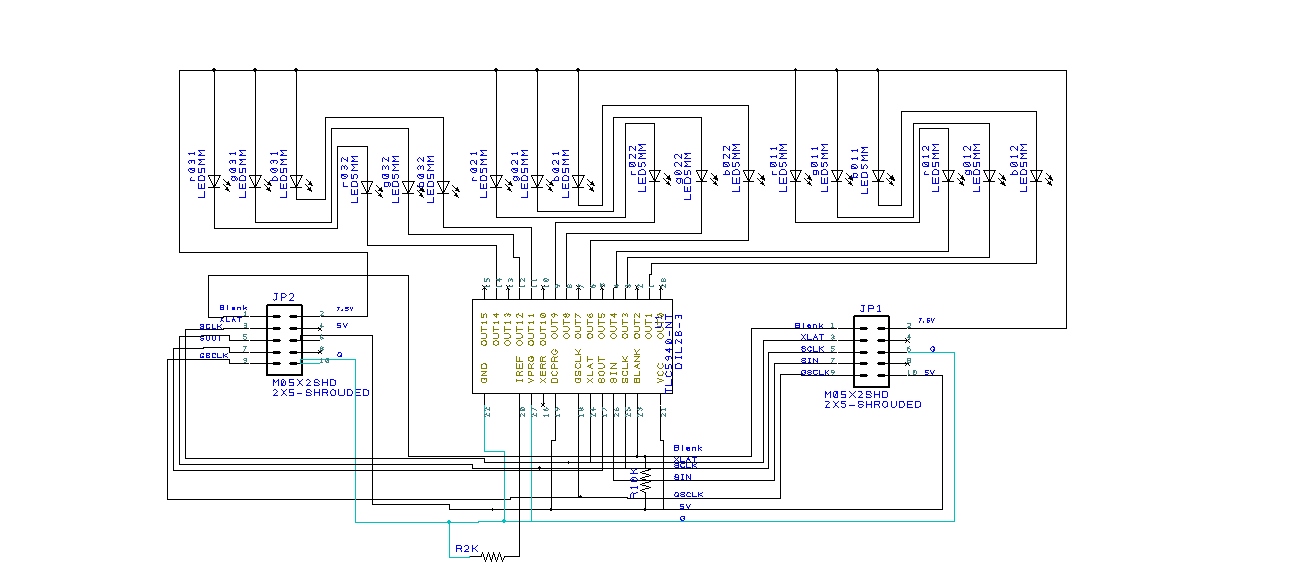
After some useful comments on both the SparkFun forum and here, I have settled on a pair of right angle headers that look like they will do the trick. (http://www.digikey.com/product-detail/en/SBH11-PBPC-D05-RA-BK/S9177-ND/1990070) I am waiting for the manufacturer to email me the more detailed spec sheet so I know how wide the header shrouding will be.
Based on some nice comments on the Sparkfun forum (https://forum.sparkfun.com/viewtopic.php?f=20&t=35239&p=0&e=0&sid=f1d731b0e9e7087fad378aa5b65d044d), I also have added some bypass capacitors to both the 5V and 7.5V lines (recommended 100 nF for 5V and both a 100 nF and 47 uF [I chose 47 instead of 100 uF because most of the 100uF ones were not rated for more that 6V]. Also recommended was that with the two extra pins for the header I should put an extra ground and 7.5 V to reduce voltage drop. I am assuming that means I connect them to each other (the two 7.5s together and the two grounds together that is).
Pending feedback I will most likely be ready to send out for my first PCB.
\

PCB design
I am trying to figure out how to connect PCBs to each other. I have posted the following question in the sparkfun forum on PCB design.
“Hi,
I am fairly new to electronics and very new to PCB design. I am trying to create a row of LEDs that are RGB controlled in small segments using a TLC5940 to either make downlighting or for lighting artwork for different effects. I will be daisy chaining up to 10 together, but I want to design my PCB to have both the LEDs and the TLC5940 on one PCB and then be able to connect to additional copies of the PCB. So all these PCBs need to lay flat in the same plane. How can I best connect PCBs to each other for this? Right now I have thrown in a shrouded 10 pin header which i could connect via ribbon wire (https://www.sparkfun.com/products/8506). but this seems like it is unnecessary and large. I need 8 pins at least. What other options are there?”
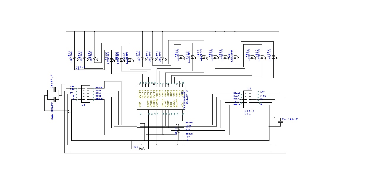
Below is my schematic that I have right now. Hopefully I can get some answers on this.
Schematic for my LED PCB
PCBs
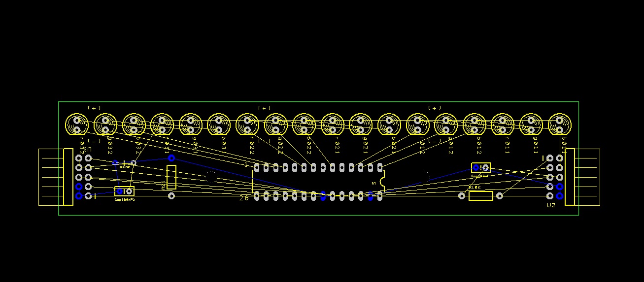
Started looking into making a PCB for the LEDs with the TLC incorporated in it. I am looking at using batchpcb.com because they are pretty cheap but have a long lead time. I have found that design spark is a good pcb design software (eagle had a maximum pcb size of 100×80 mm and I need at least 150 mm for all the LEDs)
Just starting
I am deciding to start this blog to chronicle my ventures into beer making and arduino projects

Recent Comments